YAP Measurements
Yet Another Poweramp
As already mentioned, one of the targets of the YAP project was to develop an amp that would not require any adjustments, other than the bias current. Therefore, the results presented throughout this section should be viewed as an out-of-the-box performances metric. No special optimization was attempted, based on these results.
1. Associated equipment.
Since the PGP amp days my basement lab grew significantly; a number of new equipment were added, some of which were used to evaluate and improve the YAP series designs. None of these equipment are though required to build a YAP amp.
- Distortions measurements (and the source for fundamental nulled spectrum analysis) are still my Amber 5500 units. One of these units was upgaraded with the IMD board, now both automatic CCIR and SMPTE intermodulation distortions are now possible.
- An Advantest R9211C is now the main audio spectrum analyzer, up to 100KHz.
- A HP89410A vector signal analyzer is the tool of choice for HF spectrum analysis, bandwidth measurements, and loop gain measurements. The HP89410A works up to 10MHz.
- A HP8702A network analyzer is used for HF impedance measurements and analysis. While the HP8702A works from 300KHz up to 6GHz, the measurements are done at much lower frequencies, usually up to 10-20MHz. The main advantage of the 8702A is the ability to display the impedance measurements in a Smith chart and also automatically separate and display (in ohm, nH and/or pF) the resistive and reactive parts of an impedance.
- The control computer was upgraded to Windows 7 x64 and the GPIB interface is now a NI GPIB ENET/100.
2. OPS Measurements
The maximum output level of the Amber 5500 audio analyzers is only 16Veff. As the OPS has an unity gain, to measure the THD up to 300W, some 50V at the input are required. I used a LME49810 high voltage driver configured as an noninverting opamp with a gain of 10 to increase the Amber 5500 output level.
For the use of these measurements, the Amber 5500 generator distortions are negligible (they are at around -112dB @30KHz). However, the HF LME49810 output distortions were not negligible (in particular because I had to overcompensate beyond the 10pF in the datasheet; that was required because the LME49810 was on a breadboard, with long wires, etc...). For the sake of the LME49810 stability, I had also to add a 330ohm resistor in series with the output. The source impedance has a significant impact on the OPS distortions, so the 330ohm value here should be considered in any eventual apple to apple comparison.
I used the first Amber 5500 to measure the distortions at the OPS input and the second at the OPS output. The analyzers bandwidths was set to 200KHz. Up to 200KHz, the OPS phase shift is negligible so all spectral input and output components are in phase. Therefore, the OPS THD20 can be computed by squarely substracting the LME49810 output distortions from the OPS output distortions.
As expected, without a driver (MJE5032/15033) BC fixed capacitor, the OPS was barely stable. In particular as the output was approaching the supply rail voltages, the OPS occasionaly bursted into oscillation, and it was only the lab power supply current limiting that saved the smoke and flames.
A 470pF fixed cap was added across each driver BC junction. This rendered the OPS unconditionally stable in any capacitive load I was able to provide, even without an output coil. The resulting gain and phase vs. frequency was determined:
Another way to skin the cat
YAP Conclusions
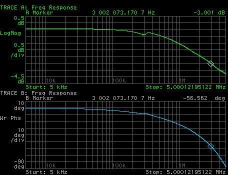
The 3dB bandwidth is about 3MHz. At this frequency, the phase shift is 56 degrees. Using a lower source impedance will increase the bandwidth, but still, given these results, to keep the poles separate, I would not recommend an overall amp unity loop gain frequency much over 1MHz. According to the simulations, I was hoping for a bandwidth of at least 5-6MHz, but probably the device models were way to optimistic... At 100KHz the phase shift is only a very few degrees, meaning that at such low frequencies the input and output spectral components can be safely considered in phase. Therefore, the input/output spectra magnitude normalization and substraction mentioned above is safely precise. The gain hump of about 1/5dB at ~300KHz is a measurement artifact.
For all these measurements, the supply rails were set at +/-60V and the OPS was biased at the Oliver point. The emitter resistors are 0.2ohm and the optimum bias for a distortion minima was found at a current of about 90mA. This is because of the rather large Rb=4.7ohm, adding an equivalent Rb/Beta to the emitter resistor. The BC drivers caps were the same 470pF.
Here are the OPS THD20 vs. frequency distortions measurements at 4ohm load:
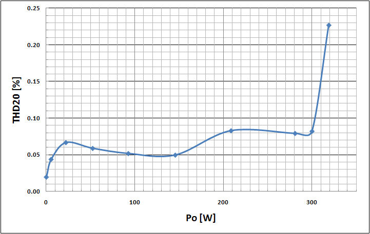
The OPS open loop distortions are under 0.1% up to 300W output power. At 200W output into 4ohm (which seems to be the worst case), the output spectra at 20KHz fundamental is:
To look at higher than the 4th harmonic, we need to go to 10KHz fundamental - that's because of the 100KHz spectrum analyzer maximum bandwidth. Here's the result:
The distortions are (of course) lower than at 20KHz, but then we have little reason to believe the spectral distribution would significantly change. The spectral component (both odd and even) are monotonically decreasing with frequency.
A very important parameter is the input impedance. The input impedance is the VAS load, and therefore it can be considered as an important fron end design input parameter. Here's the OPS input impedance measuremet, represented in Smith chart:
The graph is qualitative only - as you can see, the input impedance is almost entire capacitive. The frequency scale is here logarithmic and the resonance close to 5MHz is due to the wiring. The measured input capacitance was (after impedance normalization) determined to be about 80pF.
We now have the results and parameters to design the YAP front end.