Low Noise Designs
Conclusions
Here are some measurement results I got on the HPS designs. You don't need to do these measurements by yourself; results are very reproductible, in particular if you use good quality components (polypropylene caps in the RIAA correction stages, good quality metal film resistors, good quality electrolytics and film caps for decoupling. The performances are almost independent on the opamp models you may use; any low noise, unity gain stable, bipolar input opamp will do. For HPS 3.1, the only constraint is to have a a maximum supply rating of +/-22V. AD797, LME49710, OPA211 (HPS 1.0 and 2.0), LME49760, LT1128, LT1115 (HPS 3.1) etc... were experimented with almost identical measurement results.
The only components that need close matching, both in absolute values and between channels are the RIAA network resistors and caps. I can confirm that channel frequency response imbalances are very easily audible and may create a significant discomfort, so I decided to select the RIAA caps as close matched as possible. Fortunately, it was enough to purchase 10pcs of each Vishay BC 2% polypropylene caps to find two pairs matched to 0.2%. 1% metal film resistors are, of course, much easier to match to 0.2%.
HPS Noise performance
The HPS's (input shorted) noise was measured using a HP3562A Dynamic Signal Analyzer. This instrument is able to measure and display directly the noise spectra and the frequency response. For each design, the gain at 1KHz was measured, at an input signal of 1mV (10mV at the 3562A output, divided by a MAX5492 10:1 resistive attenuator. The results were very close to the theoretical/calculated values:
Low Noise Measurements
These gain values were used to normalize the measured output noise spectra, the result being the equivalent input noise at 1KHz. Note that this noise is not necessary the plateau noise of the base amp (without RIAA correction) which is actually slightly lower. However, the equivalent input noise at 1KHz seems to be a good indicator of the overall noise performance, and also correlates much better with the listening tests results.
I also did some measurements on gain, phase and noise performance before installing the RIAA correction caps and the 50KHz pole cap, using a HP89410A Vector Signal Analyzer. The frequency response is flat +/- 0.5dB to about 1MHz (as designed) and the corner noise frequency is always around 1...3KHz (typical for JFETs). The noise density frequency dependence of 10dB/decade confirms that the noise is essentialy 1/f. No signs of shot noise or any other types were identified, and that's a good sign that the JFETs bias at relatively low Vds was well chosen.
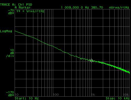
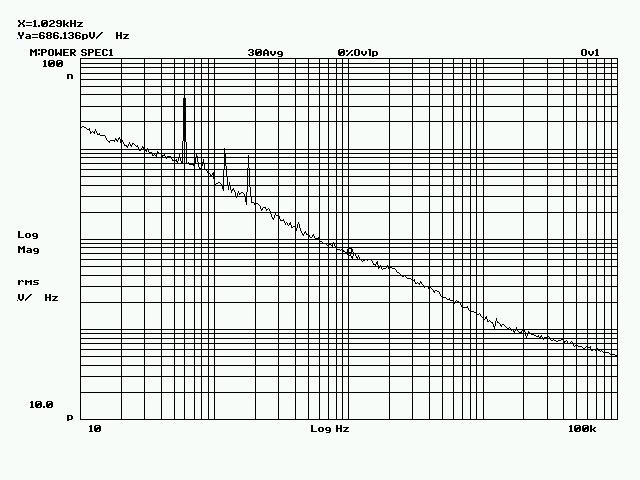
HPS 1.0 equivalent input noise spectra for the MM gain setting:
The HPIB plotter simulator is unable to print the special characters, so you have to imagine the sqrt, greek letters, etc... symbols.
Noise is 1nV/rtHz, which is very good for MM cartridges. Compare this with the NAD PP-3 phono stage noise below (the gain is 32dB, therefore the equivalent input noise is around 8nV/rtHz).
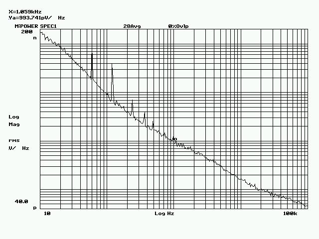
The HPS 1.0 MC gain setting noise:
The same 1nV/rtHz, but the harmonic noise components are now visible up to the 8th mains frequency harmonic. At these levels, the harmonic noise is audible in high efficiency speakers, from 1m. Therefore, HPS 1.0 is an excellent solution for MM cartridges only. Though, I would like to mention again that I am looking at these results with an extremely critical eye; 90% of the MC phono stages available on the market, even in the multi-thousands price range, have about the same level of harmonic noise (aka "hum"). So at the end of the day it's you to decide: if you don't use 100dB sensitive horn speakers and don't run your setup at very high output levels, you may very well never hear the faint hum and hiss I am talking about here.
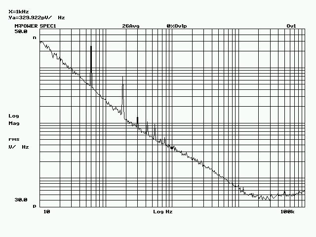
HPS 2.0 equivalent input noise, on the MM gain setting, is represented below:
The noise is slightly under 0.7nV/rtHz, while the harmonic hoise is about 6dB better than in HPS1.0. This is clearly the benefic effect of the power supply hosted in a separate case.
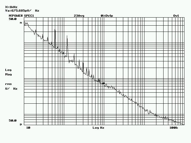
On the MC gain setting, the equivalent input noise is about the same:
These results qualify HPS 2.0 as a very good MC phono stage, in fact it is better/quiter than most of the commercial phono stages I was able to measure, with the notable exceptions of the Vendetta Research and the Pass XONO.
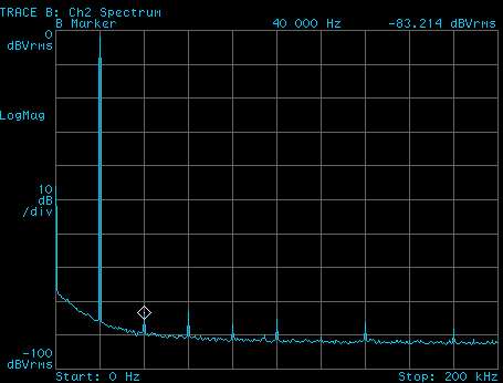
HPS 3.1 equivalent input noise is reperesented below:
0.33nV/rtHz, which is probably a new record for a MC phono stage. If you compare the last two graphs, you'll notice that HPS 3.1 has no even mains frequency harmonics, and the general harmonic noise performance is another 6-8dB better comparing to HPS 2.0 The reason of the faint odd mains harmonics are the mains transformers hosted in the same case, while the lack of even harmonics can be attributed to a single board (signal chain plus power supply) board and a superior wiring and grounding technology. The harmonic noise was more in depth analysed and here's the result:
These are the input equivalent harmonic components. As you can easily notice, the 60Hz and the 180Hz components are dominant, at 5nV and 1.3nV levels. Everything else is under 0.2nV so those components are, from any practical perspective, numbers only. Considering the worst case of a ultra low output (100uV) Ortophon MC cartridge, the signal to low frequency harmonic noise ("hum") ratio at the input is 87dB.
These are excellent results and lead to a dead silent phono stage, with no audible hiss or hum even in 100dB sensitive speakers, ear on the grille. HPS 3.1 is at par or better to the Vendetta Research and Pass XONO (my two reference implementations). However, the XONO has the power supply hosted in a separate case ($$$), while the Vendetta research had a faint audible hum in my Klipsch RF-83 horns.
Some people find easier to compare wideband and A-weighted S/N ratios, rather than the equivalent input noise; this also seems to be the method of choice in the audio magazines that publish measurements (although they are, in this respect, usually far from consistent). Anyway, the table below summarizes the S/N measurements I did on all HPS phono preamps (Wideband means a 20Hz-20KHz bandwidth). Nothing really spectacular here, HPS 2.0 has a S/N equal to the Pass XONO spec (makes sense, they both use 4 paralleled Toshiba low noise JFETs per channel), and of course, HPS 3.1 is proportionally better. I've added at the end of the table a column with the measured equivalent input noise @ 1KHz values, averaged over both channels. As expected, most of the noise is low frequency, easily removed by A-weighting filtering.
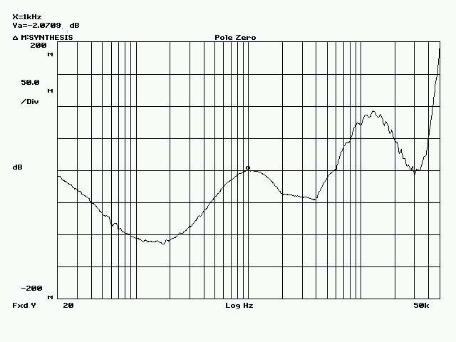
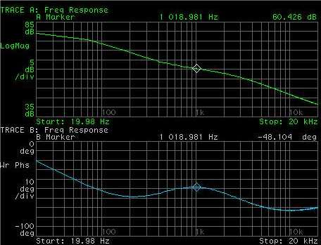
The slightly larger than 0.1dB rolloff at low frequencies is due to the interstage caps (this was actually measured on HPS 2.0); rest assured HPS 3.1 does not have this rolloff, due to the lack of any caps in the signal path.
The +/-0.1dB RIAA target was clearly reached.
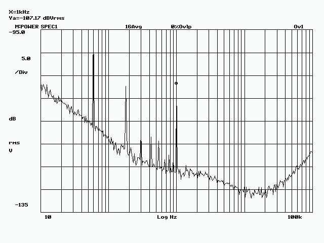
HPS 3.1 crosstalk
The HPS 3.1 cross talk was measured, under heavy overload (38mVpp input, corresponding to an about 40Vpp output) at 1KHz. The crosstalk was still at -107dB which is excellent. At normal signal levels (to an under 1Vpp output), the crosstalk at 1KHz is under -130dB (it's actually buried in noise).
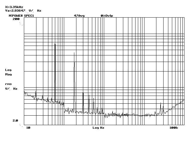
HPS 3.1 harmonic distortions
It is very difficult to measure the HPS harmonic distortion numbers at normal signal levels. Due to the high gain, the measurements are affected by artifacts and resolutions down to the ppm levels are impossible to obtain (at least with my equipment).
Instead, I measured the distortions again under heavy overload conditions, and here is the result:
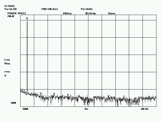
THD at 1KHz is around 0.01% The harmonic content does not extend over the 4th harmonic. As you can see, the fundamental was at 11.58Veff (16.3V peak) for this test. By extrapolating these results, the distortions at 1KHz and normal output levels ( around 1V) should be not more than 0.001%.
These are numbers inpossible to beat in a non-feedback design. In fact, all commercial phono stages that I was able to measure have distortions larger by about an order of magnitude. Do I hear the anti-feedback crowd mumbling again?
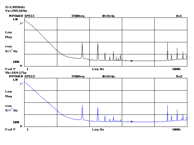
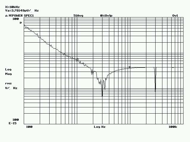
HPS 4.1 Noise
By using bipolar low noise devices, HPS 4.1 is further improving the noise performance. The equivalent input noise (before instaling the RIAA correction components) is represented below:


HPS RIAA response
The HPS phono stages RIAA response is identical to all models and determined by the RIAA correction circuit components precision. I already mentioned at the beginning of this section that these are the only components that need matching, both in absolute values and across chanells. Ideally, this should be 0.1% but I found that a 0.2% matching is keeping the RIAA response within +/-0.1dB of the theoretical response.
To measure the RIAA response, first the frequency response of the phono stage was measured. The 3562A DSA has synthesis capabilities, so I used this feature to calculate the ideal RIAA frequency response (including the extra 50KHz pole). Bot measured and calculated responses are normalized to the 1KHz measured gain, then the ratio is calculated and displayed. Here is a typical result, for 0.2% component matching (the results are in milli dB!):
|
|
HPS 1.0 |
HPS 2.0 |
HPS 3.1 |
HPS 4.1 |
|
MM Gain [dB] |
44.3 |
44.3 |
N/A |
N/A |
|
MC Gain [dB] |
64.3 |
64.3 |
60.8 |
60.4 |
Midband equivalent input noise voltage is 0.29nV/rtHz, significantly better than HPS 3.1. This was achieved without any component sorting or matching.
Being a bipolar construction, it is natural to consider the input current noise, and here are the results:
The RIAA correction was already installed, so the increase of the current noise with frequency is masked by the RIAA gain drop at high frequencies.
Anyway, the equivalent input current noise @1KHz is about 5pA/rtHz and 3.7pA/rtHz @10KHz. This maps to a negligible current noise contribution to the total noise, for a 10-20ohm and usual inductance MC cartridge.
However, for a MM cartridge having 500ohm, the current noise contribution is 2.5nV/rtHz, which adds to the 0.3nV/rtHz input voltage noise and the 2.8nV/rtHz cartridge noise. This clearly shows that HPS 4.1 is not recommended for MM cartridges. OTOH, using something of the HPS 4.1 complexity for a MM cartridge doesn't make much sense anyway. A simple, low noise JFET construction with a gain of 40dB (like HPS2.0) will do just fine.
|
|
Avg. Output Noise Power [nV^2] |
Total Output Noise [uV] |
Gain [dB] |
S/N [dB] ref. 1mV |
S/N [dB] ref. 0.5mV |
En @ 1KHz [nV/rtHz] |
|
|
Wideband |
A-Weighted |
Wideband |
A-Weighted |
|
Wideband |
A-Weighted |
Wideband |
A-Weighted |
|
|
HPS 1.0 MM |
1.50 |
0.11 |
38.73 |
10.49 |
44.3 |
72.5 |
83.9 |
66.5 |
77.9 |
0.95 |
|
HPS 1.0 MC |
130.00 |
12.11 |
360.56 |
110.05 |
64.3 |
73.2 |
83.5 |
67.1 |
77.4 |
0.95 |
|
|
|
|
|
|
|
|
|
|
|
|
|
HPS 2.0 MM |
0.29 |
0.03 |
17.03 |
5.83 |
44.3 |
79.7 |
89.0 |
73.7 |
83.0 |
0.65 |
|
HPS 2.0 MC |
24.72 |
2.35 |
157.23 |
48.48 |
64.3 |
80.4 |
90.6 |
74.3 |
84.6 |
0.65 |
|
|
|
|
|
|
|
|
|
|
|
|
|
HPS 3.1 MC |
5.94 |
0.44 |
77.07 |
20.98 |
60.8 |
83.1 |
94.4 |
77.0 |
88.3 |
0.32 |
|
|
|
|
|
|
|
|
|
|
|
|
|
HPS 4.1 MC |
5.75 |
0.39 |
75.80 |
19.7 |
60.4 |
84.1 |
95.5 |
78.0 |
89.5 |
0.28 |
HPS 4.1 RIAA
For the purpose of HPS 4.1, the RIAA components were selected to 0.2% precision using a HP RLC bridge, working at 1KHz. A slight improvement over HPS 3.1 was obtained:
Except for a small dip between 100-200Hz, the 20-20KHz RIAA errors are well withing +/-0.1dB (the Y scale is 0.05dB/div). Again, if one doesn't want the 50KHz Neumann pole, just don't install C213.
The overall RIAA gain and phase are "by the book":
HPS 4.1 harmonic distortions
Harmonic distortions are considerably improved over HPS 3.1. This is both because the JFET nonlinear Ciss (not included in the feedback loop) is now absent and also because of the larger loop gain. Here's the 20KHz distortions, at 0dB = 5V output (that is, x100 the nominal input of 0.5mV @ 20KHz). All spectral components are well below 100ppm (-80dB) and are decreasing over frequency.
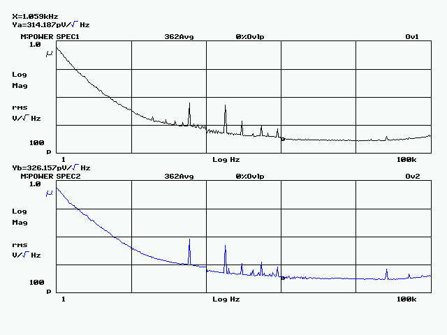
HPS 4.2 Noise
As already mentioned, HPS 4.2 has the same noise performances as HPS 4.1 The construction though (in particular the power supply) is simpler and smaller
Here's the HPS 4.2 equivalent input voltage noise measurement (before installing the RIAA correction). 0.29nV/rtHz and 0.26nV/rtHz respectively, pretty much at par with HPS 3.1. The noise corner frequency is though lower.
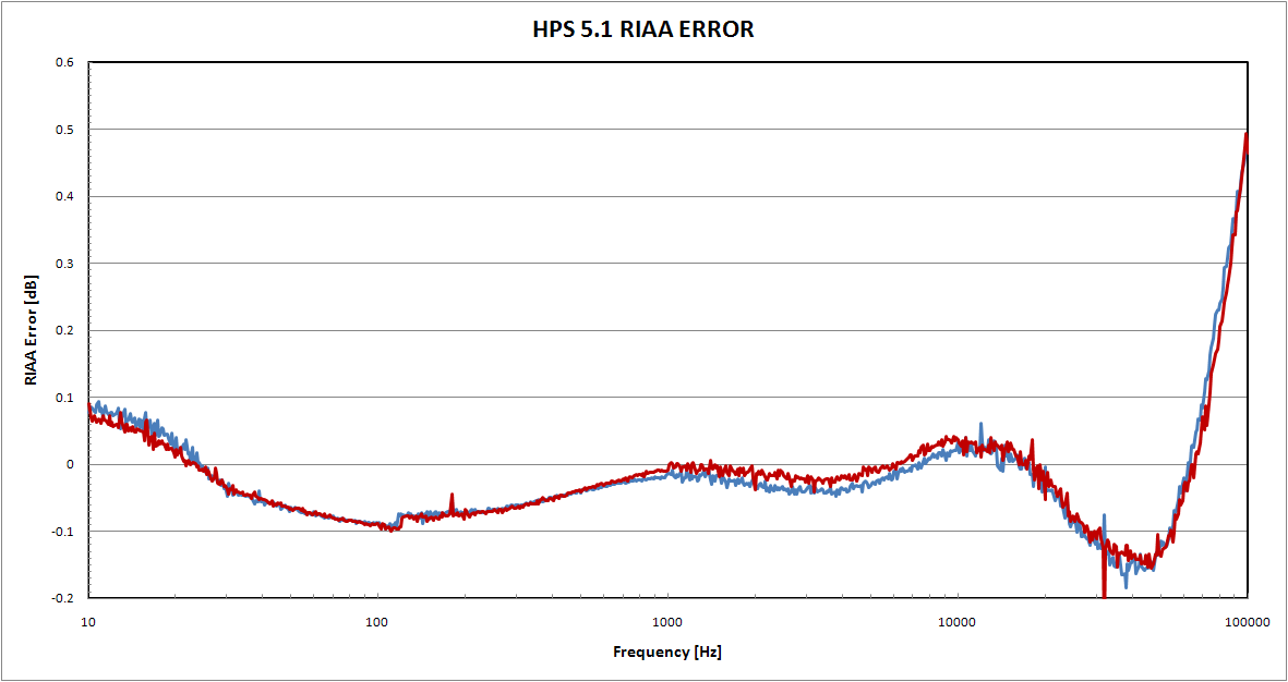
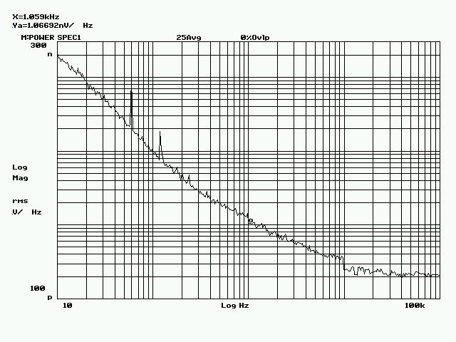
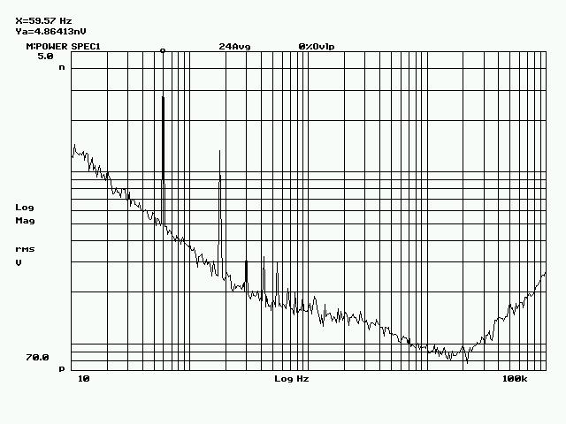
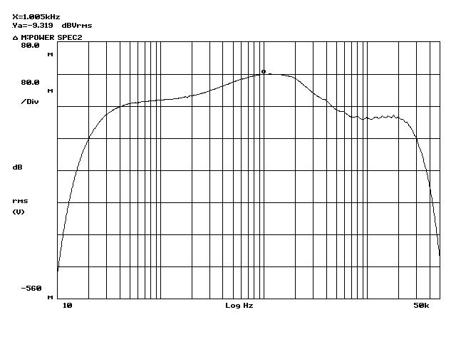
HPS 5.1 Noise
HPS 5.1 has the noise very similar in shape (but lower, due to the BF862 higher transconductance and lower noise) to HPS 3.1. The corner frequency is remarkably low, another proof that BF862 is an excellent low noise JFET. Also note the very low level of harmonic noise (50Hz plus odd harmonics). This is a direct result of a tight SMD construction.
HPS 5.1 RIAA
The RIAA error in HPS 5.1 is as low as you can ever practically get: better than 0.1dB from 10Hz to over 70KHz. This comes as a result of using 0.1% precision thin film resistors and carefully sorted C0G and polypropilene caps (in the RIAA network and for the Neumann pole). The small hiccup around 100 Hz is a measurement artifact.
As already mentioned elsewhere, if you don't like the Neumann pole, simply don't install C211/C311.