Wiring this amp is no small job. It is critical that the wiring design follow some well established rules (no ground loops, star ground connections, separate signal and dirty ground connections, etc...
Some of these provisions are considered from the early PCB design stages. Both the EC OPS boards have separate signal and power grounds. The signal ground is connected through a hum reduction resistor to the signal ground in the proximity of the amp input. Also, all power supply connections have matching power ground connections, for twisting the pairs and avoiding magnetic field sensitive loops.
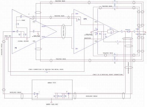
Click on the image below to get a full view of the amp wiring schematic (one channel only). The parasitic element values are informational only. We found that 2ft. of #14 wire has an inductance of about 1uH. This is a typical value for the amp boards wired on the bench. Of course, the final values for a cased amp should be much lower. You can download all schematics here.
Wiring the Beast


The signal ground is connected to the case metal ground close to the input RCA jack. Also connected to the metal case is the heatsink. Because of the 2SK1058/2SJ162 pinout (the source is connected to the heatsink plate) there is a significant capacitive load (measured to 420pF for six output devices) between the output node (before the Zobel network) and the power ground. This capacitance is defined by the heatsink insulating pads (we are using Berquist Sil-Pads), together with the parasitic series inductance of the power wiring (if over 0.5uH each) can lead to nasty stability issues. It is therefore recommended that the amp output to be floating, while the input reference is the signal ground. To clarify the situation, in the schematic above we represented all the parasitic elements and the connection to the Amber 5500 distortion analyzer. A single ended Amber 5500 output is used to feed the amp, while for the analyzer input, an Amber 5500 floating input is used.
Even so, we found the wiring as the critical setup issue. At 1ppm and below, the wiring positioning (most likely through the mechanism described by Douglas Self in Chapter 14 of his book), the wiring length (through the parasitic inductances) and the ground connections are largely impacting the measured performance. It should be clearly understood that carefully planning and executing the amp wiring is as important as the circuit design.
Now it's time for the final assembly! For cost reasons, we used a Bud Industries 4RU enclosure. The photos here (warning: large page ahead) are illustrative for our approach; you may use any other solutions as well. The only caveat (beyond what was already mentioned above) is to add an inch to the OPS power wiring. Tweaking their position may dramatically impact the THD. Keep those wires perpendicular to any other signal wires, otherwise you will face the evil magnetic fields effect.


The Ultimate Audio Amp
From Genesis to Revelation